
STEM Class 1: Introduction to Microcontrollers
Overview
A class that introduces students to microcontrollers, electronics (digital and analog) through practical hands on lessons and exploration
People
Lead instructor: Breanna Anderson (breanna@glyphstone.net)
Assistant Instructors: Ben & Paul
Getting Started
Setting up your system:
Install Mu code editor:
Helpful Web pages and files
Zoom Link
https://us02web.zoom.us/j/84670711808?pwd=UmFiL2Jna0dtQmxROXdQc1N0c1FiUT09
Class Notes
Class 1: Your Kit and setting up your computer
Class 1A : Setting UP
Class goal: When you are done, you will know basically what is in your kit, and you will have the Mu editor installed on your computer and “talking” to your “itsy-bitsy” microcontroller.
Class 2: First Program, Intro to Mu editor and board pinouts
First Program:
----------------------------------
import time
import board
from digitalio import DigitalInOut, Direction, Pull

print("Hello my first blink program!")
led = DigitalInOut(board.D13)
led.direction = Direction.OUTPUT
led.value = True

while True:
    time.sleep(1)
    led.value = not led.value
------------------------------------
Class 3 Digital I/O
Board Pinout : https://learn.adafruit.com/introducing-adafruit-itsybitsy-m4/pinouts

Button Program
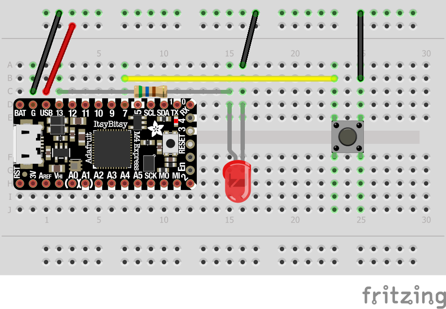
The button program is for the Button Circuit Layout below. In that circuit layout an external LED is wired “in parallel” with the onboard, red led to provide for better visibility.
Second, an external button is added to allow signals to be sent to the your ItsyBitsy controller. The button is connected to board Pins D7 (Digital 7) and to ground so that when you press the button pin7 is set to False. In the program below configures pin D7 as an Input, with a Pull-Up configuration. The program control loop then reads the button value (True, by default or False when pressed) and sets the LED value to the opposite (led.value = not buttonValue) then waits for .1 second (1/10th of a second) and the does it again over and over.
the print statement allows you to see the value of the button pin D7 if you open up the serial display window.
from digitalio import DigitalInOut, Direction, Pull
import time
import board

print("Hello my button program")
button = DigitalInOut(board.D7)
led = DigitalInOut(board.D13)
led.direction = Direction.OUTPUT

button.direction = Direction.INPUT
button.pull = Pull.UP

led.value = False
while True:
    buttonValue = button.value
    print(buttonValue)
    led.value = not buttonValue
    time.sleep(.1)
Button Circuit Layout
Stem Class 9: May 3, 2021
Programming, Variables, math and stuff and using the REPL (Read, Execute, Print Loop)
Toggle Button Program
In this program we expand on the Button circuit and button program above to show how we can have the light “toggle” on and off each time we press the button. In order to make this happen. we need to keep information in the program that can help us determine when the button was pressed for the first time since either starting or being released. We use a “variable” named lastButtonPress for that purpose and set it’s initial value to True, which is the default button press state.
We also need to keep track of the “state” of the button as being “On” or “Off”. The variable " buttonState keeps track of this and is set to False or Off by default.
Every time we press the button down we want the light to “toggle” between On and Off , and then from Off to On the next time we press it and so on….
import time
import random
import board
from digitalio import DigitalInOut, Direction, Pull
print("Hello my Toggle Button Program")
button = DigitalInOut(board.D7)
led = DigitalInOut(board.D13)
led.direction = Direction.OUTPUT
button.direction = Direction.INPUT
button.pull = Pull.UP
led.value = True
buttonState = False
lastButtonPress = Truewhile True:
buttonPress = button.value
if buttonPress != lastButtonPress :
print( f"Button Change: {buttonPress}")
lastButtonPress = buttonPress
if buttonPress == False:
buttonState = not buttonState
led.value = buttonState
time.sleep(.01)Using The Read, Execute, Print Loop (REPL)
Open the Serial Window
Press <CTL-C> then <Enter>

Press [Control+C] then [Enter] and you will see the >>> "prompt”

type >>> help()
Class 9: Analog I/O
In this episode we will look a working with variable voltages, reading these signals as ways of sensing the outside world. and acting on it.
Analog I/O Breadboard Layout

Exercise Schematic Diagram
About the Schematic Diagram: This is a more “universal” view of the circuit we have created in the bread board that uses symbols. I think you can see that i looks a lot simpler then the breadboard layout and it helps us to see what is “going on” a bit easier.

Pins:
AREF: The AREF pin is an Analog REFerence voltage output intended for purposes just like this. Under regular conditions (like this) it’s output voltage is 3.3 Volts, the operating voltage of the processor. It can be configured for a different voltage through software but we aren’t going to do that here. We use AREF as our reference voltage source.
GND (Ground) pin is our reference for the negative or Ground (0 Volts) reference source.
A1 (Analog 1) pin is our input to sense analog signals (meaning we want to read the voltage level presented to the pin and not just whether the voltage is High (True) or Low (False). When we use an Analog pin we can read any voltage from 0V (Ground) to the AREF voltage (in this case 3.3) and the code will read this as a number. When the voltage presented at pin A1 is 0V, the number that can be “read” from the pin is 0. When the voltage at the pin A1 is 3.3V the number that is read from the pin is 65535. That’s an odd number right? Well, that number is the largest number that can be represented by 16 bits (2 bytes) if only positive numbers are to be represented (no negative numbers). This is the “resolution” of the Analog-To-Digital (ADC) converter built into the processor . That means that every bit of the ADC output represents 3.3V/65536 = .000,05V, (aka 50 micro-volts) or 50 thousands of a volt. Wow! That’s precise!
Components:
R1 - 10K Ohm resistor- (Brown-Black-Orange). Just a plain ol’ resistor.
R2 - A photo-resistor , also called a light-dependant-resistor (LDR). This component has a resistance that varies from about 100K Ohms when it’s completely dark, to about 2K Ohms when it’s brightly lit. This is a cool little device. It does not matter which end you use as an input or output unlike an LED which cares about current direction and has a + and - lead. This makes it easier to work with.

Photo-Variable Resistor
The Circuit:
In the schematic, as in the bread-board layout you can see that the circuit is simply connecting the photo-resistor and the (regular) resistor “In Series”. We will talk more in a later class about ways that we can connect resistors together in a circuit. But series means essentially “end-to-end”. The free end of the photo-resistor is connected to AREF which is our voltage source (3.3V) . The free end of the 560 ohm resistor is connected to Ground (0V). Finally we connect the point where the two resistors meet to A1. This allows the controller to “sense” the voltage at this point in the circuit. We know the voltages at each end of the series of these two resistors: 3.3V for the “top” end and 0V at the “bottom” end. The voltage difference between the one and and the other will cause current to flow through the circuit we imagine from Top to Bottom like water flowing in a pipe.
Voltage Dividers:
A circuit like the one we have built is called a “voltage divider”. We can measure the voltage at the mid-point where the two resistors meet. That voltage will be somewhere between the supply voltage on one end and Ground (0Volts) on the other end. What that voltage is, depends on the value of the two resistors. If both resistors have the same value, then the voltage at the mid-point will be 1/2 the supply voltage: 3.3V/2 or about 1.65V. When one or both of the resistors can change, then the voltage at the mid-point of the voltage divider will also change.
We will discuss in a future lesson the logic and the math behind Voltage, Resistance and Current but here is a quick thumbnail for now:
When Current (measured in Amps) flows through a Resistor (measured in ohms), it causes a Voltage drop from one end to the other. The higher the current, for a given resistor, the greater the voltage drop.
On the other hand, with a given Voltage, the lower the Resistance, the greater the current flow and conversely the higher the resistance the lower the current flow through it.
Analog I/O Program
# Light Sensor Program - Analog I/O Demonstration
import time
import board

# Import the modules we need for this program
from digitalio import DigitalInOut, Direction, Pull
from analogio import AnalogIn

# Becuase!
print("Hello my Light Sensor Program")

# Set up the Pins: 1 Analog Input and 1 Digital output (LED)
lightPin = AnalogIn( board.A1 )
ledPin = DigitalInOut( board.D13 )
ledPin.direction = Direction.OUTPUT

# Turn off the LED
ledPin.value = False

#Our program Loop, repeated every 0.1 seconds
while True:
    # read the value of the analog input A1 (a value from 0 to 65535)
    lightVal = lightPin.value
    # calculate the voltage that this represents
    voltage = lightVal * 3.3 / 65536
    #print the voltage as a "tuple" so it will be graphable
    print( (voltage,))
    # set up a "trigger" condition to turn on the LED if the voltage goes under 1 Volt
    if( voltage < 1.0):
        ledPin.value = True
    else:
        ledPin.value = False

    time.sleep(0.1)

